Reverb Algorithms Tips
One of my aim of the Freeverb3 Project was to develop the multithreaded fast convolution algorithm and FIR filters,
which seems to have been achieved. Though we can use a lot of computer resources to process signals and can use
very long FIR filters and reverbs, the old reverbs like Lexicon 224, EMT 250 are still often used by many people and are producing
very good sounds. I think some of the reasons is that they had low-frequency low-multibit A/D D/A converters (DAC/ADC)
and random generators to produce many types of modulations. It seems that the low-multibit DAC/ADC add "warm sounds".
In contrast, the FIR filters which are used in convolution processings are very accurate but do not produce
random modulations, which may give the reverb sounds "natural tastes". This is why some convolution reverb effects
have modulation effects internally and are produing some good reverb effects. The oversampling algorithm in the
Freeverb3 algorithmic reverbs like freeverb/nrev/strev may produce input signal-related aliasing sounds which may add some
warm sounds to reverb sounds.
The articles below have been collected from many sites, which may give you some deep insight into the IIR algorithmic reverbs.
It seems that the newest commercial reverb's algorithms use modulated FIR convolutions for early reflections
and modulated allpass/comb filters based FDN + feedback tank loop IIR filters for late reverb sounds.
Algorithms for reverb processings
From the music dsp's site (which was posted by Sean Costello):
- Parallel comb filters, followed by series allpass filters.
- This was the original design by Schroeder, and was extended by Moorer. Has a VERY metallic sound for sharp transients.
- Several allpass filters in series (also proposed by Schroeder).
- Also suffers from metallic sound.
- 2nd-order comb and allpass filters (described by Moorer).
- Not supposed to give much of an advantage over first order sections.
- Nested allpass filters, where an allpass filter will replace the delay line in another allpass filter.
- Pioneered by Gardner. Haven't heard the results.
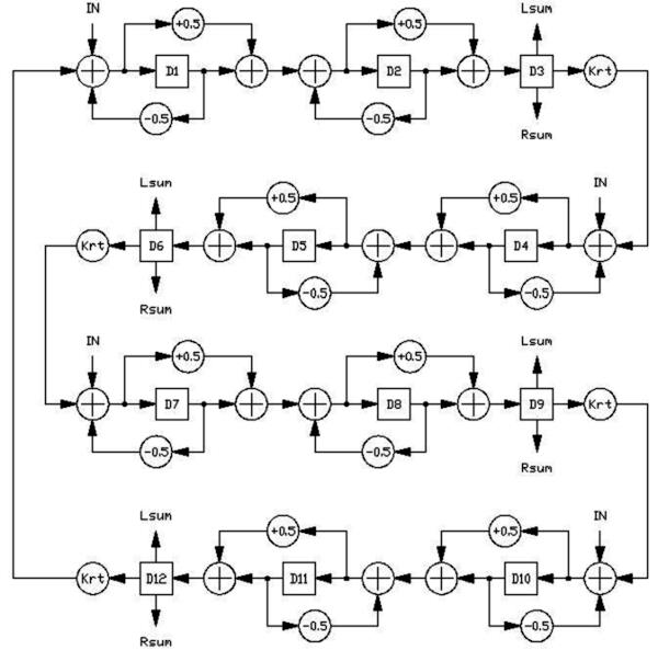
- Strange allpass amp delay line based structure in Jon Dattorro article (JAES).
- Four allpass filters are used as an input to a cool "figure-8" feedback loop,
where four allpass reverberators are used in series with a few delay lines.
Outputs derived from various taps in structure. Supposedly based on a Lexicon reverb design.
Modulating delay lines are used in some of the allpass structures to "spread out" the eigentones.
- Feedback Delay Networks.
- Pioneered by Puckette/Stautner, with Jot conducting extensive recent research.
Sound VERY good, based on initial experiments. Modulating delay lines and feedback matrixes used to spread out eigentones.
- Waveguide-based reverbs, where the reverb structure is based upon the junction of many waveguides.
- Julius Smith developed these. Recently, these have been shown to be essentially
equivalent to the feedback delay network reverbs. Also sound very nice.
Modulating delay lines and scattering values used to spread out eigentones.
- Convolution-based reverbs
- The sound to be reverbed is convolved with the impulse response of a room,
or with exponentially-decaying white noise. Supposedly the best sound, but very computationally expensive, and not very flexible.
- FIR-based reverbs.
- Essentially the same as convolution. Probably not used, but shorter FIR filters
are probably used in combination with many of the above techniques, to provide early reflections.
Information on digital reverb structures
Posted on Eventide by froombosch
Before digital Reverb
Adding a reverb to a dry sound has been very polular and there are different ways to add reverb.
Reverb is used to make a something sound like in a space and to add a nice colour or more power to a sound.
The obvious way to make a reverb is to build a room and place speakers and microphones.
In a lot of 50-60 studios these rooms are build and with use reverb dampening devices
the colour or the needed reverb time could be reached. Other ways of making a reverb is by using
a plate reverb like the EMT-140 (1957)/240 (1970) where a metal plate is exited and the
movement (=sound) of the plate recorded. These kind of reverb has a very dense sound and needs
a predelay and added early reflections. Tapedelays or the Binson Echo machine was used for predelay or early reflections.
Digital reverb
In the 60-ties Moorer and Schroeder worked on different structures build in digital domain to recreate reverbs.
In some papers the classical reverb structures where setup. These structures involve series and parallel
all-pass and combfilters. When you are trying to test these structures they mostly are not really usable
for audio applications because they are very metallic sounding. Or as quoted in the SP2016 website:
We experimented with a couple of different 'patches' creating several variations on the Schroeder
theme but with no real improvement. But the basic can be used and where used with some of the early digital reverbs.
The first commercial available digital reverb: the EMT 250
Barry Blesser and Karl-Otto Bader designed the algorithms of this machine.
The resources in computertechnology were very basic as there where only
16K memory chips available. The algorythm structure is based on the next series: predelay -->
three diffusers build around allpass filters --> reverb tank build around three series of
4 delays (tanktime between 80-120 ms). The output of the third delaytap is feedbacked to the
input and in this feedback loop there are high and low filters added. The outputs of the delays are put
into a schroeder decorrelator and has four outputs. Dynatron has build a remake and there are several
replicas in different machines. The patent gives more information on the delay times.
The amplitude is exponetially decaying. I'll add more information later. A rebuild can be made in Vsig.
Jusst by using these building blocks it is possible to make it sound like the EMT. Calculating the gains
for every delay tap and the filters in the feedback is the biggest work. I am happy with spreadsheets....
The second one Quad Eight CPR-16
There is no information on this reverberator, beside that it sounds pretty crude.
The Third: Ursa Mayor Space station STS-282
Chris Moore explained a lot on this structure on his website. The structure is based around a 24-tap delay.
Fifteen of these delaystaps are modulated (with 62 microseconds steps) and 8 are not. These 8 are probably summed
and form the output. The space station is know for a gritty but usefull reverb. There is a remake build.
How deep the mudulation is and the waveform of the modulation is not clear to me. Need to do more research on it.
Later Ursa Mayor was sold to AKG and they build the AKG ADR 68K
Lexicon 224 (1978)
The Lexicon 224 was the design of Dr. Griesinger. I have not found a lot of information on this structure.
The d'Attoro paper gives more insight on the basic structure of the lexicon structure.
Matlab Implementation of Reverberation Algorithms. Fernando A. Beltran, et al.
After these first three units others where jumping onto the reverbs:
Dynacord vsr-23, Sony DRE-2000, MXR etc.etc.
Eventide SP2016 (1982) The Princeton site gives not a lot of information, besides that it is not a variation on the Schoeder theme.
Quantec QRS (march 82) This German compagny does not give a lot of information on the structures.
The fun thing about these early reverberators is that some of these sound so good.
The EMT 250 is still in use in a lot of studios and some swear by it. A lot of remakes are build,
some in the form of hardware machines, some in the form of software.
Harrie Munnik Studio Froombosch
Lexicon ARU
Some Lexicon hardware information from DIY Audio sites:
The room reverb looks just like Griesinger 'plate' reverb
covered by the AES paper 'Effect Design - Part 1, Reverberator and other filters'. Except that there is one additional stage of diffusion and one
additional stage of delay through each leg of the tank. Also, the placement of the damping low-pass filters are somewhat different.
The input diffusion is done differently. Rather than having four cascaded input diffusors, there are two
pairs of cascaded diffusors, each feeding one leg of the tank. Both are fed from the predelay line. The output tap summation uses a lot more taps,
including some in the predelay.
Also of note - the PCM60 addressing system does not have a facility for
modulation of delay taps, which makes the modulating delays impossible. Other
Lexicon units can - the 'slave' processor can update the control store at will.
The function of a separate slave processor is to do exactly that - update the
control store at a moment's notice. But the PCM-60 uses a ROM control store without a control processor at all.
Note that a double precision multiply flushes the pipeline at the end, which
is why it is used for the initial scalar multiply *0.5000. Also, double
precision multiply offers accumulator clearing functions which are not present
in the single-precision MAC instruction.
Turns out that the PCM70 is almost identical to this PCM60. Except that the
processor (a Z80) can reload the program 'at will' which is useful for modifying
parameters. The master Z80 contains
the user interface. The slave processor
(another Z80) contains the DSP microcode, LFO's, and a bunch
of parameter updating functions. It also has some of the presets stored in it.
The two EPROM's are literally full.
Looking at this design, and especially the timeframe they were done in, is a
lot like looking at Mr. Wozniak's Apple II logic design, and the group coding
disk controller card. Those were awesome designs and the way the old ARU was put
together reminds me of what good design is.
The same architecture is used on the 224XL, 200, and the ARU IC's in the
PCM60, PCM70, and the 480. The later Lexicons (300, PCM80, 81, 90, 91) use a new 'lexchip',
which looks to be a single-chip implementation of a PCM70 ARU with one
additional state in the multiplier - a Lexichip uses four clocks per cycle,
which makes the multiplier precision any one of 4-bit, 5-bit, 7-bit, or 8-bit,
depending on the timing bits set in the microcode. The microcode for the Lexichip1 is very similar, though not identical to,
the ARU system on the 480L. Some control bits are missing to make room for
generating the raw ADC/DAC timing signals and memory bank selection. I don't
think they significantly affect programming it, though. Note that the 224XL ARU is significantly
different... yet not really. The 200, PCM60-70-480 ARU's are practically
identical - the 480 uses an additional T-state per instruction, allowing one
more multiplication, whereas the PCM-70 is an updated PCM-60. The 224XL allows two multiplier bits at once, and has a dedicated
shift register rather than single registers with rewired inputs.
Different Lexicons used different program lengths. The 224
used 100 program steps, the PCM60 and 70 used 128 steps, the 480 uses 80 steps
but with four processing cores, the 300 (using two Lexichips) used a 96 step
program, and the PCM91, which uses two Lexichips as well, allows all 128 steps.
A Lexchip-3 appears to
offer 256 program steps per loop rather than the 128 steps for the
older ARU-based units.
Another interesting thing marginally related to this is the AL3201 digital
reverb. It follows many of these principles in hardware design, however, almost
two decades of 'progress' has made transistors cheap enough that a fast (and
cheap) 7-bit plus sign multiplier very practical.... which is what the AL3201
does. There are fewer temporary registers (just enough, though, to help in
making reverb logic like diffusors, comb filters, allpass filters, etc. The
128-byte per sample code length is shared with the Lexicon 'verbs, although the control store on the
AL3201 is in RAM - much like a PCM70. I may try running one of these chips when
I get around to it.... when I have some time. Note that the added efficiency of
the AL3201 is offset by the shorter data RAM page size, meaning that the DRAM
needs to have instructions specifically added to refresh the dynamic memory used
for storage. That makes the PCM-60 room algorithm take around 110 out of 128
instructions. Also, the audio data memory is stored in a floating-point format.
Finally, it also contains four LFO's which would allow modulating delays to be
implemented without processor intervention. It also offers a linear
interpolation feature which allows LFO sample switching to be a bit smoother.
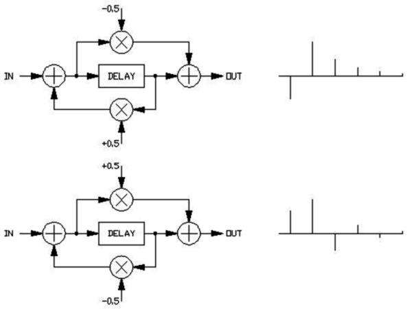
A diffusor in the AL3201 can be written more efficiently than in the Lexicon
reverb. Two lines of code are required.
RAPB diffend k=-0.40625
WBP diffstart k=0.40625
The first line fetches the end of the diffusor, stores that in B.
Simultaneously, it multiplies that by -0.40625 and adds it to the accumulator.
The next line stores the accumulator into the data memory, *then* takes the
accumulator, multiplies it by 0.40625, and adds it to the B register, and stores
that into the accumulator. Voila, instant diffusor in two lines.
Now, I'm not about to start distributing any Lexicon code... I only posted a
small snippet that you see here - so don't go asking for any more of it. I've
been in trouble for posting too much reverse engineered information before. Up
to this point, it's educational.
History of allpass loop / "ring" reverbs
Posted on
Spin Semiconductor Forum by seancostello
seancostello Mon Sep 11, 2006 10:12 pm
Hi:
I have been studying and implementing digital reverbs since the late 1990's. Most of the articles on digital
reverbs have tended to discuss either Schroeder structures, or feedback delay networks (Puckette, Jot).
Yet it seems like a large number of commercial reverbs are based around having several allpasses in a comb
filter loop, with the reverb time determined by the gains within the loop, and the input signal diffused by
series allpasses. In some implementations, the output is taken from the end of the comb loop, while in other instances,
the output is taken from a number of weighted delay taps from within the loop (the input to the loop may also be
injected at various points).
The example reverbs for the FV-1 appear to be based around this allpass loop topology, and the description
at the spinsemi knowlegebase
is the best I have ever read about this technique.
My question is, when was this structure developed? Was it developed by one person and then passed on
/ reverse engineered, or was it developed in multiple places independently? I haven't been able to figure
this out, as I have very few bits of "secret sauce" when it comes to reverb - most of what I have learned
is from the published information, although I have picked up a few tidbits from trade shows.
Any info about the history of this structure would be greatly appreciated.
Regards,
Sean Costello
P.S. Here is a brief history of the allpass loop structure, from an outsider's (nerdy) perspective:
1972 - Michael Gerzon publishes algorithm techniques in Studio Sound, showing how a feedback delay
network can be made allpass, and how allpass feedback delay networks can be embedded within larger
feedback delay networks. The 2-part article can be viewed as a theoretical basis of the allpass
loop designs (as well as feedback delay networks), but doesn't seem to have been read by many people.
David Griesinger cites this paper, and I know Christopher Moore read it post-SST design
(my scan of the article has "Property of Christopher Moore" stamped on it).
1978? - Lexicon 224 released, with algorithms by David Griesinger.
Presumably this uses the allpass loop topology - see Dattorro info.
1992 - Bill Gardner publishes master's thesis, where he describes reverbs based around allpasses
within comb loop, with taps taken out from delay line. Gardner alludes to fact that this technique
was something he picked up working within industry, possibly Kurzweil.
1995 - Jon Dattorro writes internal documentation for Ensoniq ESP2 chip, describing a plate reverb
topology based upon allpass loops. The initial topology was based upon reverse engineering a Lexicon 224,
according to another Ensoniq engineer.
1997 - Dattorro publishes work from internal document in Journal of Audio Engineering Society,
complete with delay line lengths. Lawsuit commences, which is ultimately settled in Dattorro's favor.
Keith Thu Sep 28, 2006 8:22 am
Sean:
Don't know much about the history, but have spent years developing commercial reverbs.
The first reference to all passes I recall was an AES issue that detailed Schroeder's work,
a terrible sounding algorythm as described. The tinny sound of the MXR reverb (my work) suffered
from this problem. Other early reverbs also suffered from this limited structure (Nichols).
Including all pass filters within the comb loops came next (in my work), which definately
improved density build, but I was having coding difficulties in the early years with multiple APs in a loop.
It only makes sense though, that the inclusion of multiple APs in a delay loop will improve density,
which in my case, was finally worked out with my Midiverb, and other later Alesis products. Finally,
the summation of multiple regenerated delays, with APs included, leads to excessive peaking at
certain frequencies... Making the reverb a single loop solves the problem.
I've found that once you're in the single loop, multiple AP arena, you can make just about anything
that has a good tail, reletively flat response, and as much final density as you like. Everything
I write today is single loop, with modifications as to input signal injection and output tap selection.
You makin' a product, or are you just interested in the history? From my point of view, it's the
guys that worked at Lexicon that made it all happen, although there were some simultaneous discoveries...
It is the all pass though, that takes the credit!
Keith
seancostello Wed Oct 18, 2006 1:18 am
Hi Keith,
Thanks for the reply! I am mostly interested in the history of such algorithms.
I have developed a lot of different reverb algorithms, but as far as I know, none
of them have made it into a product (I work for a DSP manufacturer, that does not have a primary focus on MI audio).
Interesting observation about the multiple parallel loops causing coloration.
I had similar results when combining several loops with multiple taps from each loop.
My analogy is having several spoked wheels, all of different sizes, speeds, and number
of spokes, interlocking. At some point the spokes will jam, which results in unpleasant resonances.
Combining loops with a unitary matrix, where each loop only contributes energy from a fixed point,
seems to help out a lot, but that is more in the FDN camp.
I am still curious about how much parallel discovery there was, versus reverse engineering,
and lore passed from engineer to engineer.
Sean Costello
Keith Wed Oct 18, 2006 9:30 am
Sean:
Sorry I can't help more. I wrote the article on the website you cited, and it's the result of my
experimentation; be advised, filters (HP and LP) within the loop greatly enhance the 'naturalness',
if that's what you're looking for.
It's the all-pass that does it. Everything comes from the flat response and complex impluse response
of the all-pass. Tapped delays will cause great difficulty, becuase of their non-flat nature.
To be used for an initial response, OK, but with feedback? Yuk!
Sorry I can't help more.
Again, are you coding, or studying history?
Keith
Sean:
Sorry, I just replied to your first message; I'm new to this forum stuff.
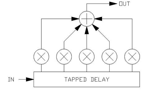
As a suggestion, think of two taps on a delay, summed to an output; this will cause certain
frequencies to reinforce where the delay between the taps causes the two outputs to be in phase,
canceling when the phase relationship is opposite. in the case of two taps, the response will be a comb,
and the gain of the peaks will be 2X, or 6dB. now imagine 3 taps, with only certain frequencies
reaching the peak gain of 3X... If many taps are taken (all with equal weights), only a few
frequencies will show reinforcement from all of the taps simultaneously, but the peak gain at
these frequencies will be quite pronounced. In a loop, such a tapped delay will end up only
producing those peaked frequencies as an output, since the recirculation will reinforce just those peaks.
As for history, I once watched the impulse response of a 224 on a scope, moved a few sliders and
realized what they were doing. Did that influence my choices? Maybe, but I'm still discovering.
In particular, lately, my emphasis is on just how little is involved to get a good sounding reverb;
it turns out to be near-trivial. The FV-1 can do a decent reverb in maybe 20 instructions.
From the algorithms I hear from other products, it appears that the best algorithms are still not widely known.
From my perspective, the nut has been fully cracked; the secret is psychoacoustics; we're simply
not equipped to deconvolve the return from an ambient space with any precision!
What's FDN?
seancostello
FDN = Feedback Delay Network.
A feedback delay network is the term usually used to describe a bunch of delay lines in parallel,
that are combined via a matrix, and the output of the matrix fed back into the intputs.
Miller Puckette and John Stautner have generally been credited with first publishing this type of algorithm in 1982,
with Jean-Marc Jot expanding on the concept in the early 1990's.
However, feedback delay networks were first described by Michael Gerzon in 1971 and 1972, but the publication
that Gerzon published in (Studio Sound) was not very common in the US at the time, so Puckette/Stautner and
Jot tend to get the credit for the discovery. Gerzon's original papers are pretty amazing
(feel free to PM me if you want copies).
With the basic feedback delay networks, you can get a very good sound with a minimum of work, provided
you know the tricks. 16 parallel delay lines, combined with a Hadamard matrix and sent back into the inputs,
creates a nice, dense sound with very little coloration.
The problem with feedback delay networks is the cost of performing the matrix computations, as well as the
memory allocations needed to compute the matrix. A 16x16 feedback matrix can take 256 computations if done
brute force; by using various tricks, you can get the cost down, but you will need at least 64 MAC operations (N*log2(N))
to create a matrix that is fully diffusive. In addition, you need to keep the outputs of the matrix around
in order to work with them, which can eat up memory space. On the FV-1, this would use up at least 16 of
the 32 registers. Using an allpass loop, or a feedback delay network with fewer branches but more density
in each branch, is a good idea in this case.
Having said this, there is a generalized matrix representation of reverberation structures, where you have
separate matrices for the inputs (feedforward), the feedback between the delays, and the outputs.
With these 3 matrices (I might be missing one or two matrices, but whatever), you theoretically can express
ANY reverberator structure - Schroeder, allpass ring, Ursa Major Space Station, what have you. For an allpass ring,
the feedback and feedforward matrices would be rather sparse, with a lot of zeros, and "triagular" sections
representing the feedback and feedforward for the allpass sections. This is pretty nifty if you have a lot
of math skills and want to have a strong theoretical analysis of your reverb structure. If
you have crappy math skills, like I do, you can ignore most of the deep matrix algebra, and just choose
a few good unitary systems that you can plug together like Legos.
Thanks for the info about watching the impulse response of the 224 on a scope! That is pretty much what
I have done to learn about reverbs - that, and track down every paper I can find. I am also finding that
my good sounding algorithms are getting simpler and simpler.
Sean Costello
puretube
here`s wondering about how it`d sound, when the allpass(-es) used in above mentioned designs weren`t of a FIX nature,
but MOVING (modulated) ? either very slow (V-LFO), or random...
the other question arises:
what if not an ordinary allpass is being inserted in the feedback path,
but half a DOME-filter (wideband phase-shifter),
whose output would never be in-phase, nor outphase with the input-signal,
so there wouldn`t be cancellation or reinforcement at certain frequencies?
[ponderings of an analog veteran... Wink ]
www.pure-tube-technology.com
seancostello
Most of the above mentioned designs use modulated delay lines in the allpasses, so you can listen to the results.
It can be hard to tell whether the modulation is very slow versus random when listening to a reverb,
due to the modulation being further diffused by the allpasses that follow the modulation in the loop.
Sometimes you can hear the characteristic sinusoidal modulation in the decay (this is audible in some of
the Creative Labs Audigy reverbs).
In general, modulated delay lines within a reverb helps to spread out the perceived resonances (or eigentones).
If you look at yer average reverb structure, the resonances are further apart then in a real room or hall,
due to the limitations placed on delay memory (the number of resonances directly corresponds to the length
of the delay lines). Modulation helps to "blur" these resonances, such that there are less perceived holes
between them. Think of the structure as a picket fence; modulation makes the pickets less defined,
and blurred around the edges, such that they are closer to touching each other.
Another way of looking at the benefits of modulation would be Keith's above explanation of the cancellation
between taps. Modulation can be used to make the effective delay between taps time-varying, such that the
cancellation frequency is constantly changing around, and therefore less noticable.
Modulating the allpass coefficient of a delay allpass is not as effective. It reduces the overall diffusion
that a given allpass adds to the system, and can result in a sound much like banging a metal pot full of water.
Half a dome filter would just result in some shifting of the resonances, but would not necessarily improve or
decrease the sound quality. A bunch of allpasses in series will simply shift the frequencies at which there
will be cancellation or reinforcement.
Sean Costello
seancostello Thu Nov 16, 2006 12:30 pm
BTW, I do hope to port my Csound Dome filter (phase differencing, or Hilbert network) to the FV-1 once
I get the development kit. Keith Barr has the code for a 6th order network in the Informal Notes section.
Mine would be 12th order, but it remains to be seen how accurate the network will be, due to the coefficient
quantization. I will presumably use the registers for the memory, in order to grab those extra 5 bits of
resolution for the multipliers.
Sean Costello
puretube Thu Nov 16, 2006 12:51 pm
Quote:
A bunch of allpasses in series will simply shift the frequencies...
is this true also for "staggered" allpasses,
like (in the analog world) so-called "univibed" allpasses?
(which in fact is what I called: "half a Dome"; i.e.: 1 branch...)
thanks a lot, anyway, for your explanation!
(didn`t know, that the allpasses in the dig. reverb were modulated;
I thought only the "pure" delaytime was being moved...).
Smile
www.pure-tube-technology.com
seancostello Thu Nov 16, 2006 2:08 pm
puretube wrote:
Quote:
A bunch of allpasses in series will simply shift the frequencies...
is this true also for "staggered" allpasses,
like (in the analog world) so-called "univibed" allpasses?
(which in fact is what I called: "half a Dome"; i.e.: 1 branch...)
It is hard to say. Allpasses in the feedback loop of a delay will do SOMETHING, but what they
do depends not just on the allpasses, but on what follows them in the feedback loop.
For these allpass ring reverberators, the delay-based allpasses have such a dramatic effect
on the phase of the signal going through them, that a small number of 1st order allpasses in the
loop will not have much of a predictable audible effect.
If you are talking about a single delay line in series with first order allpass filters and feedback
around that system, the effects can be far more pronounced. I have done spring reverb simulations in
this way (I had to use a few hundred 1st order allpasses, though).
Time varying 1st order allpasses will also have a noticable effect in most systems, depending on where
the coefficients are modulated. In addition, a fixed 1st order allpass can be used to obtain a fixed
fractional delay length, which might be useful.
Sean Costello

